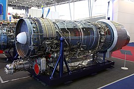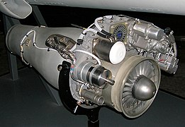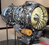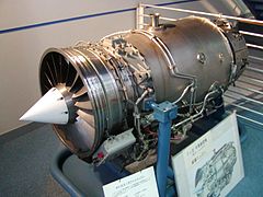
Turbofan
A turbofan or fanjet is a type of airbreathing jet engine that is widely used in aircraft propulsion. The word "turbofan" is a combination of the preceding generation engine technology of the turbojet, and a reference to the additional fan stage added. It consists of a gas turbine engine which achieves mechanical energy from combustion,[1] and a ducted fan that uses the mechanical energy from the gas turbine to force air rearwards. Thus, whereas all the air taken in by a turbojet passes through the combustion chamber and turbines, in a turbofan some of that air bypasses these components. A turbofan thus can be thought of as a turbojet being used to drive a ducted fan, with both of these contributing to the thrust.
Not to be confused with propfan or turboprop.
The ratio of the mass-flow of air bypassing the engine core to the mass-flow of air passing through the core is referred to as the bypass ratio. The engine produces thrust through a combination of these two portions working together; engines that use more jet thrust relative to fan thrust are known as low-bypass turbofans, conversely those that have considerably more fan thrust than jet thrust are known as high-bypass. Most commercial aviation jet engines in use are of the high-bypass type,[2][3] and most modern fighter engines are low-bypass.[4][5] Afterburners are used on low-bypass turbofan engines with bypass and core mixing before the afterburner.
Modern turbofans have either a large single-stage fan or a smaller fan with several stages. An early configuration combined a low-pressure turbine and fan in a single rear-mounted unit.
Overall performance[edit]
Cycle improvements[edit]
Consider a mixed turbofan with a fixed bypass ratio and airflow. Increasing the overall pressure ratio of the compression system raises the combustor entry temperature. Therefore, at a fixed fuel flow there is an increase in (HP) turbine rotor inlet temperature. Although the higher temperature rise across the compression system implies a larger temperature drop over the turbine system, the mixed nozzle temperature is unaffected, because the same amount of heat is being added to the system. There is, however, a rise in nozzle pressure, because overall pressure ratio increases faster than the turbine expansion ratio, causing an increase in the hot mixer entry pressure. Consequently, net thrust increases, whilst specific fuel consumption (fuel flow/net thrust) decreases. A similar trend occurs with unmixed turbofans.
Turbofan engines can be made more fuel efficient by raising overall pressure ratio and turbine rotor inlet temperature in unison. However, better turbine materials or improved vane/blade cooling are required to cope with increases in both turbine rotor inlet temperature and compressor delivery temperature. Increasing the latter may require better compressor materials.
The overall pressure ratio can be increased by improving fan (or) LP compressor pressure ratio or HP compressor pressure ratio. If the latter is held constant, the increase in (HP) compressor delivery temperature (from raising overall pressure ratio) implies an increase in HP mechanical speed. However, stressing considerations might limit this parameter, implying, despite an increase in overall pressure ratio, a reduction in HP compressor pressure ratio.
According to simple theory, if the ratio of turbine rotor inlet temperature/(HP) compressor delivery temperature is maintained, the HP turbine throat area can be retained. However, this assumes that cycle improvements are obtained, while retaining the datum (HP) compressor exit flow function (non-dimensional flow). In practice, changes to the non-dimensional speed of the (HP) compressor and cooling bleed extraction would probably make this assumption invalid, making some adjustment to HP turbine throat area unavoidable. This means the HP turbine nozzle guide vanes would have to be different from the original. In all probability, the downstream LP turbine nozzle guide vanes would have to be changed anyway.
Thrust growth[edit]
Thrust growth is obtained by increasing core power. There are two basic routes available:
Improvements[edit]
Aerodynamic modelling[edit]
Aerodynamics is a mix of subsonic, transonic and supersonic airflow on a single fan/gas compressor blade in a modern turbofan. The airflow past the blades must be maintained within close angular limits to keep the air flowing against an increasing pressure. Otherwise air will be rejected back out of the intake.[50]
The Full Authority Digital Engine Control (FADEC) needs accurate data for controlling the engine. The critical turbine inlet temperature (TIT) is too harsh an environment, at 1,700 °C (3,100 °F) and 17 bar (250 psi), for reliable sensors. Therefore, during development of a new engine type a relation is established between a more easily measured temperature like exhaust gas temperature and the TIT. Monitoring the exhaust gas temperature is then used to make sure the engine does not run too hot.[50]
Blade technology[edit]
A 100 g (3.5 oz) turbine blade is subjected to 1,700 °C (3,100 °F), at 17 bar (250 psi) and a centrifugal force of 40 kN (9,000 lbf), well above the point of plastic deformation and even above the melting point. Exotic alloys, sophisticated air cooling schemes and special mechanical design are needed to keep the physical stresses within the strength of the material. Rotating seals must withstand harsh conditions for 10 years, 20,000 missions and rotating at 10 to 20,000 rpm.[50]
Fan blades[edit]
Fan blades have been growing as jet engines have been getting bigger: each fan blade carries the equivalent of nine double-decker buses and swallows air the equivalent volume of a squash court every second.
Advances in computational fluid dynamics (CFD) modelling have permitted complex, 3D curved shapes with very wide chord, keeping the fan capabilities while minimizing the blade count to lower costs.
Coincidentally, the bypass ratio grew to achieve higher propulsive efficiency and the fan diameter increased.[51]
Rolls-Royce pioneered the hollow, titanium wide-chord fan blade in the 1980s for aerodynamic efficiency and foreign object damage resistance in the RB211 then for the Trent.
GE Aviation introduced carbon fiber composite fan blades on the GE90 in 1995, manufactured since 2017 with a carbon-fiber tape-layer process.
GE partner Safran developed a 3D woven technology with Albany Composites for the CFM56 and CFM LEAP engines.[51]
Future progress[edit]
Engine cores are shrinking as they operate at higher pressure ratios and become more efficient and smaller compared to the fan as bypass ratios increase.
Blade tip clearances are more difficult to maintain at the exit of the high-pressure compressor where blades are 0.5 in (13 mm) high or less; backbone bending further affects clearance control as the core is proportionately longer and thinner and the fan to low-pressure turbine driveshaft space is constrained within the core.[52]
Pratt & Whitney VP technology and environment Alan Epstein argued "Over the history of commercial aviation, we have gone from 20% to 40% [cruise efficiency], and there is a consensus among the engine community that we can probably get to 60%".[53]
Geared turbofans and further fan pressure ratio reductions may continue to improve propulsive efficiency.
The second phase of the FAA's Continuous Lower Energy, Emissions and Noise (CLEEN) program is targeting for the late 2020s reductions of 33% fuel burn, 60% emissions and 32 dB EPNdb noise compared with the 2000s state-of-the-art.[54]
In summer 2017 at NASA Glenn Research Center in Cleveland, Ohio, Pratt has finished testing a very-low-pressure-ratio fan on a PW1000G, resembling an open rotor with fewer blades than the PW1000G's 20.[53]
The weight and size of the nacelle would be reduced by a short duct inlet, imposing higher aerodynamic turning loads on the blades and leaving less space for soundproofing, but a lower-pressure-ratio fan is slower.
UTC Aerospace Systems Aerostructures will have a full-scale ground test in 2019 of its low-drag Integrated Propulsion System with a thrust reverser, improving fuel burn by 1% and with 2.5-3 EPNdB lower noise.[53]
Safran expects to deliver another 10–15% in fuel efficiency through the mid-2020s before reaching an asymptote, and next will have to increase the bypass ratio to 35:1 instead of 11:1 for the CFM LEAP. It is demonstrating a counterrotating open rotor unducted fan (propfan) in Istres, France, under the European Clean Sky technology program.
Modeling advances and high specific strength materials may help it succeed where previous attempts failed.
When noise levels are within existing standards and similar to the LEAP engine, 15% lower fuel burn will be available and for that Safran is testing its controls, vibration and operation, while airframe integration is still challenging.[53]
For GE Aviation, the energy density of jet fuel still maximises the Breguet range equation and higher pressure ratio cores; lower pressure ratio fans, low-loss inlets and lighter structures can further improve thermal, transfer and propulsive efficiency.
Under the U.S. Air Force's Adaptive Engine Transition Program, adaptive thermodynamic cycles will be used for the sixth-generation jet fighter, based on a modified Brayton cycle and Constant volume combustion.
Additive manufacturing in the advanced turboprop will reduce weight by 5% and fuel burn by 20%.[53]
Rotating and static ceramic matrix composite (CMC) parts operates 500 °F (260 °C) hotter than metal and are one-third its weight.
With $21.9 million from the Air Force Research Laboratory, GE is investing $200 million in a CMC facility in Huntsville, Alabama, in addition to its Asheville, North Carolina site, mass-producing silicon carbide matrix with silicon-carbide fibers in 2018.
CMCs will be used ten times more by the mid-2020s: the CFM LEAP requires 18 CMC turbine shrouds per engine and the GE9X will use it in the combustor and for 42 HP turbine nozzles.[53]
Rolls-Royce Plc aim for a 60:1 pressure ratio core for the 2020s Ultrafan and began ground tests of its 100,000 hp (75,000 kW) gear for 100,000 lbf (440 kN) and 15:1 bypass ratios.
Nearly stoichiometric turbine entry temperature approaches the theoretical limit and its impact on emissions has to be balanced with environmental performance goals.
Open rotors, lower pressure ratio fans and potentially distributed propulsion offer more room for better propulsive efficiency.
Exotic cycles, heat exchangers and pressure gain/constant volume combustion may improve thermodynamic efficiency.
Additive manufacturing could be an enabler for intercooler and recuperators.
Closer airframe integration and hybrid or electric aircraft can be combined with gas turbines.[53]
Rolls-Royce engines have a 72–82% propulsive efficiency and 42–49% thermal efficiency for a 0.63–0.49 lb/lbf/h (64,000–50,000 g/kN/h) TSFC at Mach 0.8, and aim for theoretical limits of 95% for open rotor propulsive efficiency and 60% for thermal efficiency with stoichiometric turbine entry temperature and 80:1 overall pressure ratio for a 0.35 lb/lbf/h (36,000 g/kN/h) TSFC[55]
As teething troubles may not show up until several thousand hours, the latest turbofans' technical problems disrupt airlines operations and manufacturers deliveries while production rates rise sharply.
Trent 1000 cracked blades grounded almost 50 Boeing 787s and reduced ETOPS to 2.3 hours down from 5.5, costing Rolls-Royce plc almost $950 million.
PW1000G knife-edge seal fractures have caused Pratt & Whitney to fall behind in deliveries, leaving about 100 engineless A320neos waiting for their powerplants.
The CFM LEAP introduction had been smoother but a ceramic composite HP Turbine coating was prematurely lost, necessitating a new design, causing 60 A320neo engine removals for modification and delaying deliveries by up to six weeks late.[56]
On a widebody, Safran estimates 5–10% of fuel could be saved by reducing power intake for hydraulic systems, while swapping to electrical power could save 30% of weight, as initiated on the Boeing 787, while Rolls-Royce plc hopes for up to 5%.[57]
Extreme bypass jet engines[edit]
In the 1970s, Rolls-Royce/SNECMA tested a M45SD-02 turbofan fitted with variable-pitch fan blades to improve handling at ultralow fan pressure ratios and to provide thrust reverse down to zero aircraft speed. The engine was aimed at ultraquiet STOL aircraft operating from city-centre airports.
In a bid for increased efficiency with speed, a development of the turbofan and turboprop known as a propfan engine was created that had an unducted fan. The fan blades are situated outside of the duct, so that it appears like a turboprop with wide scimitar-like blades. Both General Electric and Pratt & Whitney/Allison demonstrated propfan engines in the 1980s. Excessive cabin noise and relatively cheap jet fuel prevented the engines being put into service. The Progress D-27 propfan, developed in the U.S.S.R., was the only propfan engine equipped on a production aircraft.


