Peripheral Component Interconnect
Peripheral Component Interconnect (PCI)[3] is a local computer bus for attaching hardware devices in a computer and is part of the PCI Local Bus standard. The PCI bus supports the functions found on a processor bus but in a standardized format that is independent of any given processor's native bus. Devices connected to the PCI bus appear to a bus master to be connected directly to its own bus and are assigned addresses in the processor's address space.[4] It is a parallel bus, synchronous to a single bus clock. Attached devices can take either the form of an integrated circuit fitted onto the motherboard (called a planar device in the PCI specification) or an expansion card that fits into a slot. The PCI Local Bus was first implemented in IBM PC compatibles, where it displaced the combination of several slow Industry Standard Architecture (ISA) slots and one fast VESA Local Bus (VLB) slot as the bus configuration. It has subsequently been adopted for other computer types. Typical PCI cards used in PCs include: network cards, sound cards, modems, extra ports such as Universal Serial Bus (USB) or serial, TV tuner cards and hard disk drive host adapters. PCI video cards replaced ISA and VLB cards until rising bandwidth needs outgrew the abilities of PCI. The preferred interface for video cards then became Accelerated Graphics Port (AGP), a superset of PCI, before giving way to PCI Express.[5]
"Conventional PCI" redirects here. For the related standard that supersedes PCI, see PCI Express.Year created
June 22, 1992[1]
AGP for graphics (1997), PCI Express (2004)
32 or 64
Half-duplex:[2]
133 MB/s (32-bit at 33 MHz – the standard configuration)
266 MB/s (32-bit at 66 MHz)
266 MB/s (64-bit at 33 MHz)
533 MB/s (64-bit at 66 MHz)
Optional
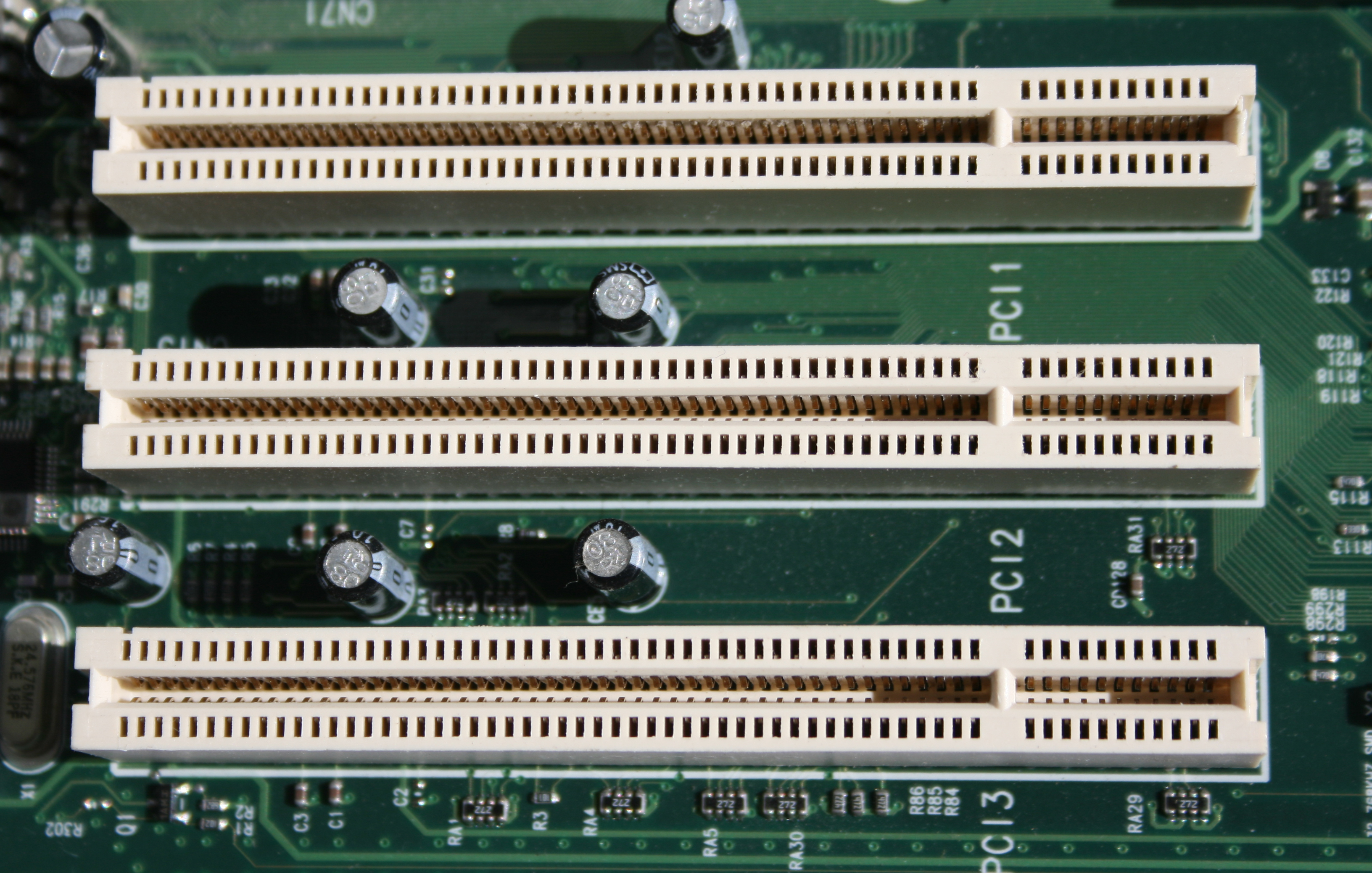
The first version of PCI found in retail desktop computers was a 32-bit bus using a 33 MHz bus clock and 5 V signaling, although the PCI 1.0 standard provided for a 64-bit variant as well. These have one locating notch in the card. Version 2.0 of the PCI standard introduced 3.3 V slots, physically distinguished by a flipped physical connector to prevent accidental insertion of 5 V cards. Universal cards, which can operate on either voltage, have two notches. Version 2.1 of the PCI standard introduced optional 66 MHz operation. A server-oriented variant of PCI, PCI Extended (PCI-X) operated at frequencies up to 133 MHz for PCI-X 1.0 and up to 533 MHz for PCI-X 2.0. An internal connector for laptop cards, called Mini PCI, was introduced in version 2.2 of the PCI specification. The PCI bus was also adopted for an external laptop connector standard – the CardBus.[6] The first PCI specification was developed by Intel, but subsequent development of the standard became the responsibility of the PCI Special Interest Group (PCI-SIG).[7]
PCI and PCI-X sometimes are referred to as either Parallel PCI or Conventional PCI[8] to distinguish them technologically from their more recent successor PCI Express, which adopted a serial, lane-based architecture.[9][10] PCI's heyday in the desktop computer market was approximately 1995 to 2005.[9] PCI and PCI-X have become obsolete for most purposes; however as of 2020 they are still common on some modern desktops for the purposes of backward compatibility and the low relative cost to produce. Another common modern application of parallel PCI is in industrial PCs, where many specialized expansion cards, used here, never transitioned to PCI Express, just as with some ISA cards. Many kinds of devices formerly available on PCI expansion cards are now commonly integrated onto motherboards or available in USB and PCI Express versions.
Interrupts[edit]
Devices are required to follow a protocol so that the interrupt-request (IRQ) lines can be shared. The PCI bus includes four interrupt lines, INTA# through INTD#, all of which are available to each device. Up to eight PCI devices share the same IRQ line (LNKA through LNKH) in APIC-enabled x86 systems. Interrupt lines are not wired in parallel as are the other PCI bus lines. The positions of the interrupt lines rotate between slots, so what appears to one device as the INTA# line is INTB# to the next and INTC# to the one after that. Single-function devices usually use their INTA# for interrupt signaling, so the device load is spread fairly evenly across the four available interrupt lines. This alleviates a common problem with sharing interrupts.
The mapping of PCI interrupt lines onto system interrupt lines, through the PCI host bridge, is implementation-dependent. Platform-specific firmware or operating system code is meant to know this, and set the "interrupt line" field in each device's configuration space indicating which IRQ it is connected to.
PCI interrupt lines are level-triggered. This was chosen over edge-triggering to gain an advantage when servicing a shared interrupt line, and for robustness: edge-triggered interrupts are easy to miss.
Later revisions of the PCI specification add support for message-signaled interrupts. In this system, a device signals its need for service by performing a memory write, rather than by asserting a dedicated line. This alleviates the problem of scarcity of interrupt lines. Even if interrupt vectors are still shared, it does not suffer the sharing problems of level-triggered interrupts. It also resolves the routing problem, because the memory write is not unpredictably modified between device and host. Finally, because the message signaling is in-band, it resolves some synchronization problems that can occur with posted writes and out-of-band interrupt lines.
PCI Express does not have physical interrupt lines at all. It uses message-signaled interrupts exclusively.